Getting impatient? Today’s hack is a little bit more techy and will require 4 LEDs, including 7-segment displays!
We will use them to count the days until Christmas in December, using Arduino and Processing.

You’ll need:
- 1 10mm red LED + resistor
- 1 10mm RGB LED + resistors
- 2 7-segment displays
- 2 shift registers
- Arduino UNO
- Jump wires
1) Getting the shift register and 7-segment display working
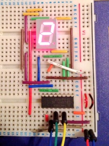
Since we are going to use 2 7-segment displays (requiring 8 pins of the Arduino each), a red LED (1 pin) and an RGB LED (3 pin), we will have to use shift registers, which let you control up to 8 LEDs (or, in our case, a 7-segment display) using only three pins of the Arduino. I must say, shift registers have become my favourite component of 2013, and if you want to know a bit more, I’ve written about them in the third section of this article.
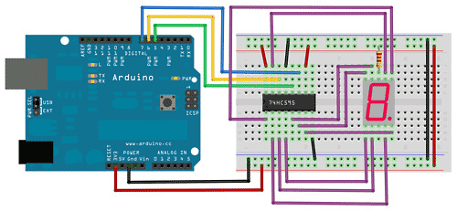
I have used the wiring found on sweeting.org, as shown below but I’ve written my own simplified sketch for it. Below is how we display numbers 0 to 9.
//Pin connected to ST_CP of 74HC595
int latchPin = 5;
//Pin connected to SH_CP of 74HC595
int clockPin = 7;
//Pin connected to DS of 74HC595
int dataPin = 6;

int sequence[10] = {192,249,164,176,153,146,130,248,128,144};
//in order, those numbers are the bits necessary to display 0, 1, 2, 3, 4, 5, 6, 7, 8, 9
//so to get a 3, we can call sequence[3]


void setup() {
  //set pins to output so you can control the shift register
  Serial.begin(9600);
  pinMode(latchPin, OUTPUT);
  pinMode(clockPin, OUTPUT);
  pinMode(dataPin, OUTPUT);

}

void loop() {
   for (int i = 0; i< 10; i++)
   {
      registerWrite(sequence[i]);
    }
}


void registerWrite(int numberToDisplay) {
    Serial.println(numberToDisplay);

    if(numberToDisplay < 257){  //we check this to avoid getting noise from the board.
      digitalWrite(latchPin, LOW);
      // shift out the bits:
      shiftOut(dataPin, clockPin, MSBFIRST, numberToDisplay);

      //take the latch pin high so the LEDs will light up:
      digitalWrite(latchPin, HIGH);
    }

    delay(1000);
}
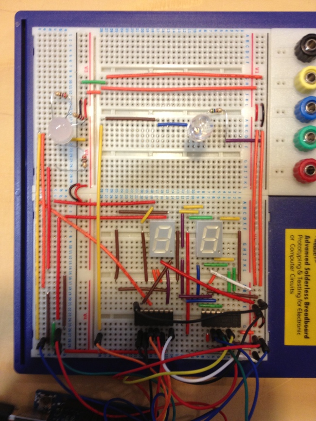
We can then add a second shift register and display, following the same wiring.
2) Checking the date with Processing
If you are not using an Ethernet shield, you can’t check the date directly from an Arduino plugged into your computer. You need to use Serial communication and a Processing sketch, along with the Time library. Although, I couldn’t get the example to work.
Having researched and written about Serial communication earlier this year, I decided to write my own Processing and Arduino sketches. Below are the commented results.
This is only going to be a December countdown, and a day by day one (although you could, on the last day, detect the hours, then minutes, then seconds to Christmas…)
The Processing sketch:
import processing.serial.*;

Serial myPort;

int d;
int m;

int target = 25; // our target date is the 25th
int diff = 0;
// this is the difference between the current date and the target date

void setup() {
  size(500,500);
  myPort = new Serial(this, Serial.list()[8], 9600); //opening the Serial port
  myPort.bufferUntil('\n');
}

void draw() {
  d = day(); // built-in Processing function that gets the computer's date
  m = month();

  if(m == 12 && d < 26) { // check that we're in December and before the 25th
    diff = target - d;
      if(diff < 10) {
        sendValue("0"+diff); //add a 0 in front of the number if it's only one digit
      } else {
        sendValue(""+diff);
      }
  }
}

void sendValue(String value) {
  myPort.write(value); //send the difference as string
  myPort.write('\n');
}
And here is our improved Arduino sketch:
//Pin connected to ST_CP of 74HC595
int latchPin = 5;
int latchTwo = 8;
//Pin connected to SH_CP of 74HC595
int clockPin = 7;
int clockTwo = 13;
//Pin connected to DS of 74HC595
int dataPin = 6;
int dataTwo = 12;


int sequence[10] = {192,249,164,176,153,146,130,248,128,144};

String diff = "";
String numberOne ="";
String numberTwo ="";
int indexOne = 0;
int indexTwo = 0;
char charbuffer[20];


void setup() {
  //set pins to output so you can control the shift register
  Serial.begin(9600);
  pinMode(latchPin, OUTPUT);
  pinMode(clockPin, OUTPUT);
  pinMode(dataPin, OUTPUT);
  pinMode(latchTwo, OUTPUT);
  pinMode(clockTwo, OUTPUT);
  pinMode(dataTwo, OUTPUT);

  registerWrite(255,255); //resets the 7-segment displays


}

void loop() {
   checkSerial();
}

void checkSerial() {
   while(Serial.available() > 0) {
    char inChar = Serial.read();

    if(inChar == '\n'){
        //split the value into to numbers that we can use as indexes from the sequence array
        numberOne = diff.substring(0,1);
        numberTwo = diff.substring(1,2);

        numberTwo.toCharArray(charbuffer, 20);
        indexTwo = atoi(charbuffer);

        numberOne.toCharArray(charbuffer, 20);
        indexOne = atoi(charbuffer);

        registerWrite(sequence[indexOne],sequence[indexTwo]);

        //resetting the value from next reading
        diff = "";
    }

    else if(inChar !='\r'){
      //getting the value from Processing
      diff += inChar;
    }

  }
}

void registerWrite(int dozenToDisplay, int numberToDisplay) {

    if(numberToDisplay < 257){
      digitalWrite(latchPin, LOW);
      digitalWrite(latchTwo, LOW);
      // shift out the bits:
      shiftOut(dataTwo, clockTwo, MSBFIRST, dozenToDisplay);
      shiftOut(dataPin, clockPin, MSBFIRST, numberToDisplay);


      digitalWrite(latchPin, HIGH);
      digitalWrite(latchTwo, HIGH);
    }
}
Now, providing that you keep the Processing sketch running in the background and have your Arduino plugged into your computer, your LEDs should display the number of days until Christmas (21 today!).
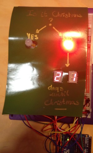
3) Building the flowchart
Finally, to spice it up, I wanted to build a flow chart, with additional LEDs, asking “Is it Christmas?”, if NO, light up a red LED and point to the number of days remaining. If YES, make an RGB LED blink with different colours.
Below is a glimpse of the final wiring, the final Arduino sketch, and a view of the result (for today, and if I change the date on my computer to December, 25th).
//Pin connected to ST_CP of 74HC595
int latchPin = 5;
int latchTwo = 8;
//Pin connected to SH_CP of 74HC595
int clockPin = 7;
int clockTwo = 13;
//Pin connected to DS of 74HC595
int dataPin = 6;
int dataTwo = 12;

//Define the LED pins
int redPin = 3;

int RPin = 9;
int GPin = 10;
int BPin = 11;

boolean isRGB = false;


int sequence[10] = {192,249,164,176,153,146,130,248,128,144};

String diff = "";
String numberOne ="";
String numberTwo ="";
int indexOne = 0;
int indexTwo = 0;
char charbuffer[20];


void setup() {
  Serial.begin(9600);
  pinMode(latchPin, OUTPUT);
  pinMode(clockPin, OUTPUT);
  pinMode(dataPin, OUTPUT);
  pinMode(latchTwo, OUTPUT);
  pinMode(clockTwo, OUTPUT);
  pinMode(dataTwo, OUTPUT);

  pinMode(redPin, OUTPUT);

  pinMode(RPin, OUTPUT);
  pinMode(GPin, OUTPUT);
  pinMode(BPin, OUTPUT);

  //turns the RGB LED off
  resetRGB();

  registerWrite(255,255);


}

void loop() {
   checkSerial();
   if(isRGB) {
     blinkRainbow(random(255), random(255), random(255));
     delay(500);
   } else {
    resetRGB();
   }
}

void checkSerial() {
   while(Serial.available() > 0) {
    char inChar = Serial.read();

    if(inChar == '\n'){
      //Serial.println(diff);
      if (diff == "00") {
        //if it's Christmas, turn the red LED off, enable the RGB LED
        isRGB = true;
        digitalWrite(redPin, LOW);

      } else {
        //if not, turn the red LED on
        redLightOn();
      }


        numberOne = diff.substring(0,1);
        numberTwo = diff.substring(1,2);

        numberTwo.toCharArray(charbuffer, 20);
        indexTwo = atoi(charbuffer);

        numberOne.toCharArray(charbuffer, 20);
        indexOne = atoi(charbuffer);
        registerWrite(sequence[indexOne],sequence[indexTwo]);

        diff = "";
    }

    else if(inChar !='\r'){
      diff += inChar;
    }

  }
}

void registerWrite(int dozenToDisplay, int numberToDisplay) {

    if(numberToDisplay < 257){
      digitalWrite(latchPin, LOW);
      digitalWrite(latchTwo, LOW);
      // shift out the bits:
      shiftOut(dataTwo, clockTwo, MSBFIRST, dozenToDisplay);
      shiftOut(dataPin, clockPin, MSBFIRST, numberToDisplay);

      //take the latch pin high so the LEDs will light up:
      digitalWrite(latchPin, HIGH);
      digitalWrite(latchTwo, HIGH);
    }
}

void redLightOn() {
  //Here you turn the "no" LED on
  digitalWrite(redPin, HIGH);
}

void blinkRainbow(int R, int G, int B){
  analogWrite(RPin, R);
  analogWrite(GPin, G);
  analogWrite(BPin, B);
  //Here you turn the "yes" LED on, the R,G and B values are drawn randomly in the loop function.
}

void resetRGB() {
  analogWrite(RPin, 255);
  analogWrite(GPin, 255);
  analogWrite(BPin, 255);

  //the RGB LED is common annode, a 255 value will turn it off
}
And that’s it, now you’ve got a nice LED display to tell you Christmas is coming!! Tomorrow we’re making a game…

Pingback: Christmas Carols | 300 LEDs before Xmas